


When the LCD screen displays an abnormality, it was previously deduced through the phenomenon and the parameters were modified. This method is time-consuming and laborious. With long storage oscilloscopes, debug LCD controllers do not have to be brain-burned. Here we share the application of ZDS4054Plus in LCD testing through practical examples.
A, LCD controller, driver works
To display characters or images on the LCD, it is necessary to output RGB data to the LCD driver through the LCD controller. The LCD driver then puts the data into the buffer, and then refreshes the LCD screen display at a rate of 60 frames per second. (Because of the characteristics of liquid crystal molecules: when fixed at a certain voltage for a long time, it will cause the liquid crystal molecules to be destroyed, so to refresh the LCD screen at a certain frequency (usually 60Hz), so the video playback frame rate Although only 23 to 30 frames per second, the TFT-LCD display refresh rate reaches 60 Hz. The LCD controller timing controls the video frame rate; the LCD driver timing controls the monitor refresh rate.)
The LCD controller controls each pixel through different combinations of row and column signals. This line scan (HYNC) signal cycle is very short (up to 40kHz-100kHz), enabling the display of stable images on the screen.
The LCD controller signal timing and working principle are as follows:
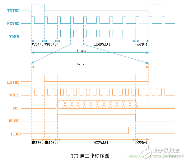
LCD controller difficult to debug? Teach you to use the oscilloscope can be easily resolved
lVSYNC: frame synchronization signal, indicating the start of scanning a frame, a frame is also a picture of the LCD display;
lHSYNC: line synchronization signal, indicating the beginning of scanning 1 line;
lVCLK: pixel clock signal, each pulse is filled with 1 pixel;
lVDEN: Data enable signal. When high, the fill data is valid.
lVD[23:0]: LCD pixel data output port.
lLEND: end of line signal;
Taking a 1024x768 pixel LCD screen as an example, the complete display of a screen image signal must include a VSYNC cycle, 768 active HSYNC cycles, and each VDEN high level contains 1024 pixel clock signals. Display problems can be checked by the frame sync signal, the frequency of the line sync signal, the duty cycle, the delay, the number of HSYNC cycles contained in each VSYNC cycle, and the number of VSCLK cycles contained in the VDEN cycle.
Second, use the ZDS4054Plus oscilloscope to solve LCD display abnormal examples
1, picture overlay, repeat
Phenomenon: Displacement, superposition, or repetition of large-scale images on the LCD display;
Cause: This situation will not generally be caused by line synchronization or the delay of the field synchronization signal, which can basically eliminate this effect. You can check if there is timing or there is a difference in the clock frequency.
Solution: The first thing you should do to meet this situation is to carefully calculate the DMA transfer parameters and accurately adapt the line and field signals.
LCD controller difficult to debug? Teach you to use the oscilloscope can be easily resolved
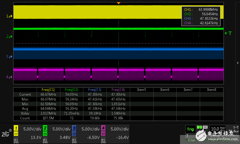
As shown in the screenshot of the oscilloscope, the corresponding signals of each channel are VCLK, VSYNC, VHSYNC, and VDEN signals in turn. The analysis steps are as follows:
1) Since a complete frame of signal time usually reaches 30ms or more, the oscilloscope needs to adjust the time base to 10ms/div, and the VCLK signal frequency is usually up to 48-96MHz, and the sampling rate must be kept at least 500Ms/s to analyze the timing. Normal oscilloscope cannot capture the waveform at this moment.
2) ZDS4054Plus can still maintain 1Gs/s sampling rate under the time base of 10ms/div, and it can perfectly restore the waveform. With the standard hardware frequency meter of each channel, it can analyze whether the frequency of each signal is abnormal;
2, image dislocation
Symptoms: The LCD display shifts in the horizontal direction, or has a few pixels of color, white, or black stripes on the top or bottom.
Reason: Generally speaking, this situation is related to frame synchronization and line synchronization signals. If it is a normal abnormality, it may be because the initialization parameters are not set correctly. If the abnormality occurs during the work process, the frame synchronization and line synchronization signals receive interference.
Solution: Check the LCD controller's line synchronization and field sync signal width, before and after delay, polarity match.
LCD controller difficult to debug? Teach you to use the oscilloscope can be easily resolved
As shown in the screenshot of the oscilloscope, the corresponding signals of each channel are VCLK, VSYNC, VHSYNC, and VDEN signals in turn. The analysis steps are as follows:
1) Through full-screen measurement and statistics, analyze the positive and negative pulse width of each signal. If the pulse width of VSYNC and VHSYNC have abnormal values, it can be judged as the display abnormality caused by the interference signal;
2) If the pulse width is normal, the number of cycles can be calculated statistically by interval measurement, and the direct mutual inclusion relationship between signals of each size cycle can be analyzed to check the timing parameters;
3) Analyze the delay between each timing signal by zoom mode and cursor measurement.


